Sports Car Tail Light Lens Cover Part 2: Creation of the Tool
In our previous blog post, we started a four-part series discussing the creation of a part from start to finish without any CAD models or prints. This week we will address how we created the tool.
Once we had the data from our reverse engineering software and a solid model had been produced, we began designing a tool. Some changes had to be made to the solid model in order to plot vacuum holes, allowing for airflow and expanding for plastic shrink.

After we had the design and customer approval, we wrote the program in Mastercam, programmed the Haas VF4, and began to make chips.
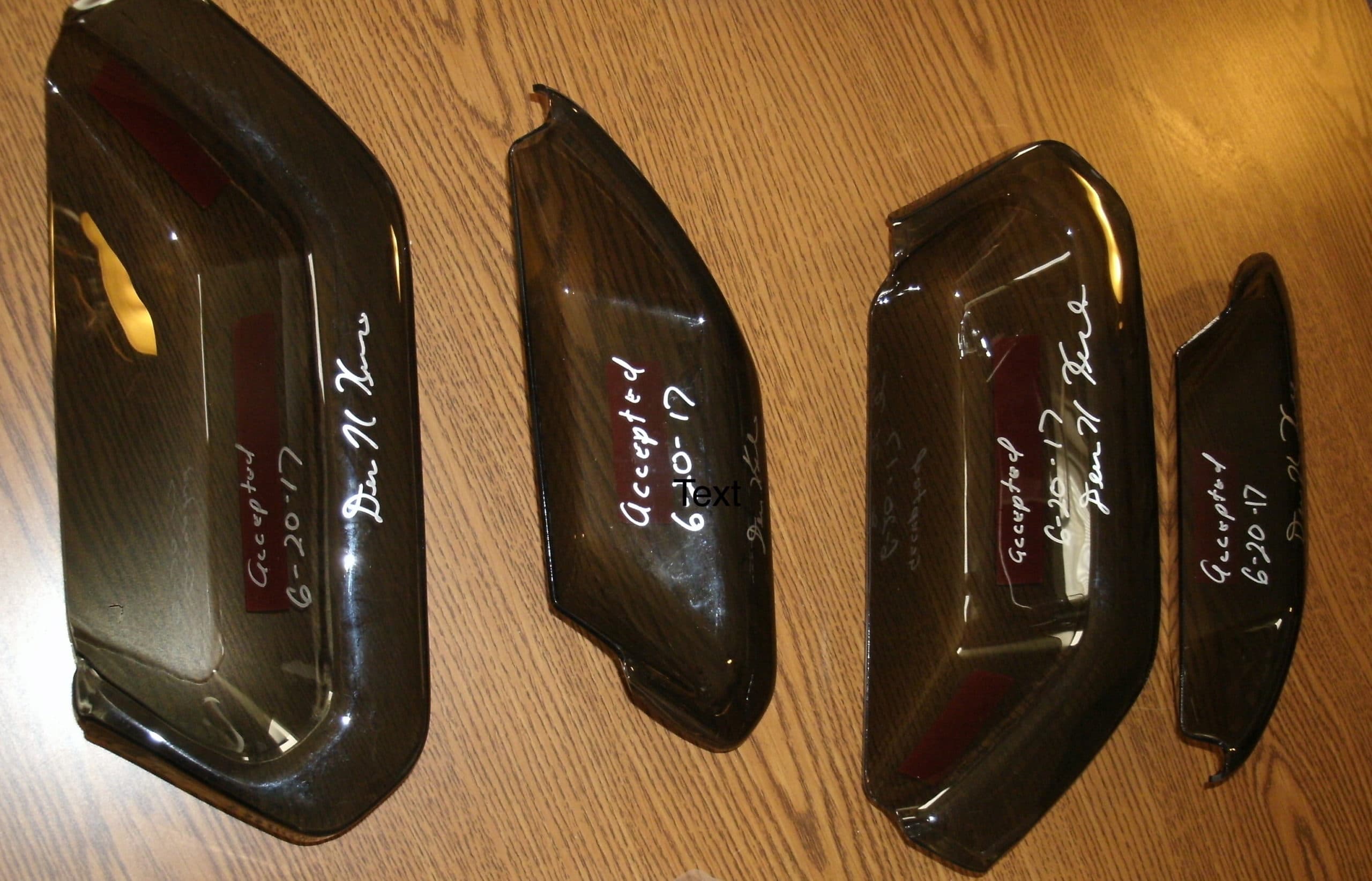
Once the tool was machined, we put in the vacuum holes required for the thermoforming plastic molding process. We were then ready to run and trim some prototype parts. (Trimming was done on our 5-Axis CNC Router.) We then submitted the prototype parts to the customer.
Upon receiving approval on the prototypes, we handed the project over to our production department. In the next blog post we will talk about the production of the parts—thermoforming, CNC trimming, and more.